An electromagnetic wave consists of a coupled oscillating electric field and magnetic field which are always perpendicular to each other. By convention, the “polarization” of electromagnetic waves refers to the direction of the electric field. In 3D geometry, arbitrary polarization is naturally defined by the prescribing the directions of all three components of the electric field.
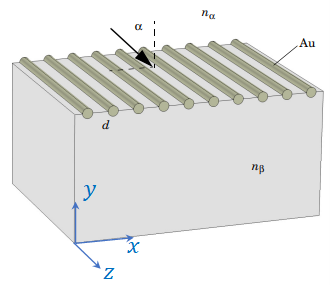
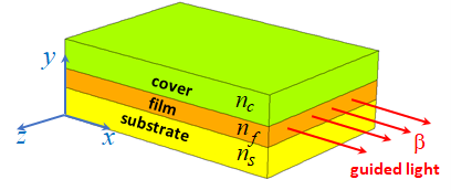
There is a broad range of problems in electromagnetics which can be solved in a 2D geometry. For example, the grating configuration shown in Figure 1 can be solved in 2D geometry. The 2D model can be constructed as a unit cell of a XY-plane slice through this geometry. Another example would be a dielectric waveguide consisting of a thin film sandwiched between a cladding cover and a substrate, as shown in Figure 2. Assuming that the width of the slab is much larger than the thickness of the layers, this waveguide problem, again can be solved in a 2D geometry as a unit cell slice in the XY-plane.
Figure 1. The grating is assumed to consist of an infinite number of infinitely long wires.
Figure 2. Three-layer asymmetric dielectric slab waveguide is a typical component in integrated optics applications.
For 2D geometry, an EM wave has two options for polarization: transverse electric (TE) and transverse magnetic (TM). For TE polarization, the electric field has only one non-zero component which is pointing in the out-of-plane direction. For TM polarization, the magnetic field has only one non-zero component and is pointing in the out-of-plane direction, while electric field has two non-zero components in the XY-plane. Schematics of TE and TM polarizations are shown in Figure 3.
Figure 3. Two possible polarization options for the dielectric slab waveguide.
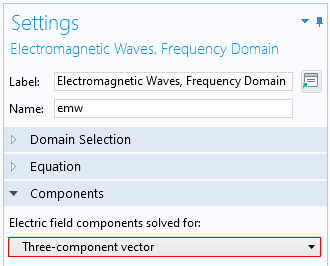
For 2D geometry, the default settings assume that both TE and TM polarizations can exist. This is because the default setting for the “Electric field components solved for” are set to “Three-component vector”, as shown in Figure 4.
Figure 4. Settings to solve for both TE and TM modes in the 2D geometry.
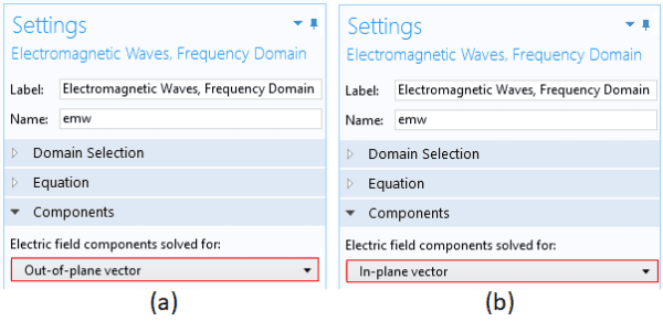
Suppose you want to extract only TE modes. To do this, you select option “Out-of-plane vector”, as shown in Figure 5a. To solve problems for only TM modes, you select option “In-plane vector”, as shown in Figure 5b.
Figure 5. Shown on the left is setting to solve for TE modes only (a). On the right is setting to solve for TM modes only(b).


