My previous blog focused on a challenging fluid dynamics problem, an area in which I have experience. However, since joining the AltaSim team, I have been learning about many other topics in physics and engineering, including acoustics. After some studying and attending our Acoustic Solutions course, I felt ready to tackle an acoustic problem, break it down, and write about the process.
A significant challenge we often face when a client approaches us with a problem is determining the right questions to ask. This is crucial to gather enough information to create an accurate simulation. In many cases, the information provided by the client is limited, and I’ve been impressed by how my colleagues can discern what information is critical and what can be sourced from academic journals.
When my colleague Sergei presented me with this acoustics problem, I initially thought he had omitted some necessary information for creating my model. However, I eventually realized he had provided enough information, even though it took me some time to recognize it.
The Challenge
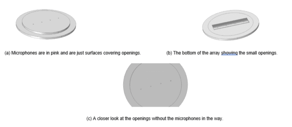
The problem statement gave me an array in an infinite baffle with microphones (the infinite baffle wasn’t provided) and stated that it operated between 500 Hz and 4 kHz. My task was to investigate the microphones’ responses 5 mm above them to an incident spherical wave at a distance of 1 m away and account for sound attenuation in the air of 0.02 dB. The array can be seen in Figure 1.
I also had to account for different incident angles, so that the spherical wave could be 1 m away anywhere between 0◦ and 90◦ from the array’s normal.
Figure 1.
My initial reaction was that I didn’t have enough information. My questions included, “What is the material of the array?” And “Do I need to use some sort of structural mechanics interface to model the microphones?” My thoughts were racing in many different directions, so I asked Sergei if he was certain he had given me all the information I needed for the model. He assured me that he had, so I realized I was thinking about this the wrong way.
I revisited the question I was trying to answer and saw that the main problem statement asked to find the microphones’ responses to an incident wave. The response can be in the form of acoustic pressure or sound pressure level (SPL). I knew I could calculate responses over a range of frequencies using a global plot group, and it seemed that the only information I needed was about pressure and SPL, at least in this instance. So, I set up nonlocal couplings of integrations over each of the four microphones and then created variables for each of these to integrate over the pressure and the SPL. The sensors can be seen in Figure 2, although I didn’t add the sensors until the end of my geometry process.
Figure 2.
Pressure acoustics is modeled exclusively within the air domains. Given that vibrations or structural mechanics were not of interest to me, I was able to construct a geometry around the array, from which I subtracted or ‘differenced’ the solid domains. Initially, I had to create an infinite baffle with the same radius as the total air sphere, which includes a layer for the artificial ‘perfectly matched layer domains.’
The realization that the infinite baffle could penetrate the entire sphere was surprising, as I hadn’t anticipated that any geometry could extend into an artificial domain. I had initially assumed it would need to truncate at the sphere’s inner layer.
The next important step in the geometry was to position this sphere with a layer and partition everything once for symmetry, and a second time to ensure that the incident wave was only on one side of the microphone, as depicted in the highlighted region of Figure 3.
Figure 3.
Figure 3 illustrates that the microphone, initially just a surface, has now become a component of the air domain. The sole material required for this model is air, as it is the only substance remaining after the solid domains have been subtracted!
All geometry building had to be done at the same time as I considered the Physics domain and boundary conditions. For example, I used an air sphere that had a layer since I chose to have Perfectly Matched Layers (PMLs) so that the scattered waves would leave without back reflection.
I could have considered other radiation condition options, such as “perfectly matched boundary” but I like to see how the domain is being truncated. I didn’t consider Spherical Wave Radiation as an option because this boundary condition isn’t recommended when you have angles of incidence far from the normal, which I did in this case.
Once the PMLs were configured, the completion of the Physics setup required the addition of a single boundary condition and one domain condition to the Pressure Acoustics, Frequency Domain interface. The first step was to introduce the incident wave by adding the Background Pressure Field domain node. As previously mentioned, this was only applied to one side of the microphone. This is logical when considering that the incident wave is unable to travel beyond the infinite baffle and microphone, and can only perceive the minor openings from that point.
I calculated the pressure amplitude under the assumption of sound attenuation, setting it equal to 1 [Pa]e, –attenuation constant * source distance. However, I nearly tripped up on the units and had to remind myself that the units for the attenuation constant are Nepers per meter.
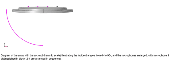
Another area where I had to exercise caution was when defining my source location. I needed to make it dependent on a changeable angle that ranged from 0° to 90°, forming a half-circle with a radius of 1 m. This necessitated the use of sines and cosines, which in COMSOL only take arguments or radians. Furthermore, when a parameter with units of degrees is saved, it’s automatically converted to radians. Therefore, conducting a parametric sweep over a parameter with a given value in degrees, and having it sweep from 0° to 90°, is not feasible (I learned this the hard way!).
Instead, I made sure to save a parameter, call it “ang,” as a unitless number between 0 and 90. When calculating the sine and cosine, I then assigned units of degrees, like this: cos(ang[deg]). I made this error a few times before getting it right! You can see an outline of the angles swept, depicted in pink in Figure 4 (the arc is drawn much closer to the array for visual clarity). The sensors are again color-coded and enlarged, and the microphone is distinguished by a black color.
Figure 4.
The final condition that I needed to incorporate was the boundary condition of Exterior Field Calculation. Even though I wasn’t concerned with the field distance from the microphones, I might have wanted to examine the array as a whole, which is external to this model. Additionally, I needed to establish the symmetry plane. Finally, I was ready for meshing! I knew that I had to sweep the PMLs and, for the other domains, I had to consider the wavelength (about 5 or 6 elements per wavelength). After meshing, I set up a parametric sweep over the angles (without specifying the unit!) and then ran the study.
The Results
We can see all different kinds of results, including the most important one I was asked for, which was the pressure at the sensors (Figure 5). We can also look at the SPLs at the same two angles (Figure 6).
Figure 5.
Figure 6.
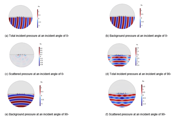
In both cases, the 90° incident angle reveals that microphone pairs 1 and 4, as well as 2 and 3, are identical. This is due to the incident wave being perpendicular to the array, introducing symmetry. This gives us all the quantitative data that we need! I also really enjoy having some lovely images for clarity, so we can add a few pictures to illustrate the total, background, and scattered pressures of the two angles under discussion (Figure 7). We can see that the total and background pressures are extremely similar for 0◦ since this angle is parallel to the array and very little gets through the microphone.
Figure 7: All of these pressures are taken at 4 kHz.
To make sure I understood this, I increased the radii of the microphones and took a quick look at the total pressure to see if this would cause an increase in pressure on the other side of the microphones (see Figure 8).
Figure 8.
The Conclusion
The most challenging part of this problem was simplifying it and taking a few steps back to understand the question before diving in to solve it. In the process, I learned new geometry techniques, such as creating an infinite baffle, and improved my acoustic knowledge. Overall, I gained a lot of new skills that I look forward to applying to future problems!


