Operating Safely: Patient Well-being
The safe and effective operation of medical devices, instrumentation and related technologies are critical to ensuring satisfactory patient outcomes and maintaining healthcare worker safety through the product life cycle. To reduce the impact of potential risks associated with the use of any new medical device or technology, regulatory bodies such as the FDA require the collation of copious amounts of supporting information. PCM&S is not only being used to ensure the initial device operation has high levels of safety and reliability, but is also being used to help identify which critical cases need to be tested experimentally to provide acceptable information for regulatory submission.
Use of PCM&S for simulation of fluid flow in devices such as pumps, catheters and valves has been used to assess the propensity for damage to the blood that could lead to an increased risk of clotting and potential organ failure. Typically, there are no standards for identifying conditions for hemolysis and consequently qualitative assessments have been made based on observations of low or stagnated flow. In contrast, assessment of thermal damage to tissue has been the subject of more extensive development of quantitative approaches to defining tissue necrosis, more information will be provided on this topic in a later section of this series of blogs.
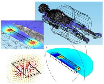
As an example of the use of PCM&S in identifying conditions under which tissue necrosis may occur, let’s consider the effect of electromagnetic fields on passive and active implanted devices, Figure 5.1.
Figure 5.1: EM field exposure of implanted medical devices.
The main ways in which the interaction of EM fields with implanted medical devices are most likely to occur are:
- Implants in patients who undergo imaging modalities such as MRI technology, where the patient is exposed to a global EM field that can be simultaneously static and dynamic
- Remote charging of devices such as pacemakers using EM coils external to the body
- Excitation of an external coil whose EM field interacts with an implant to heat a local volume of tissue and deliberately cause tissue necrosis of tumors
In these applications the presence of the device or implant can perturb the distribution of the EM field or lead to induced fields, both of which can cause local heating around the device or hinder correct operation.
The strong EM fields associated with MRI operation can also place additional constraints on device designs that must be satisfied to achieve regulatory approval. For devices with potential exposure to an MRI field, any passive implanted device has to provide MRI safety labeling; there are a few exceptions, but the requirement for safety labeling is expanding not shrinking. At the moment the major focus of the MRI safety requirement is centered on vascular devices, orthopedic implants and gastrointestinal devices.
The main areas that must be addressed for MRI safety compatibility are:
- Heating due to exposure to the EM field developed by the RF coil
- Displacements/Forces on the device from the EM fields to ensure the device does not move from its prescribed location
- Disruption to the image quality
The most significant of these is RF induced heating associated with excitation from the RF coil of an MRI. These generally operate at either 64 MHz for a 1.5T machine or 128 MHz for a 3T machine, and currently safety approval requires the manufacturer to provide standardized test results for the devices under consideration.
Thus, depending on the type of product, development of acceptable information may result in the need for many hours of time consuming and expensive physical testing. An orthopedic spinal stabilization system may contain large numbers of rods, connectors, screws and nuts, each combination of which may have to be tested and the limiting temperature rise verified. Alternatively, for an implanted stent there may be fewer numbers of products but there would still be a requirement to perform extensive testing of the range of different lengths of the product.
The mismatch in properties between the implantable medical device and the surrounding tissue perturbs the local distribution of the externally imposed EM field. This perturbation results in local heating at specific locations along the device; for a simple geometry in the shape of a straight wire, maximum heating will be observed at the ends of the device, for more complex geometries this simplified thermal distribution will be dependent on geometric complexity and material inhomogeneity.
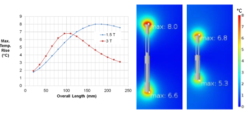
PCM&S can be used to accurately predict the interaction between the EM field developed by the RF coil of an MRI machine and an implanted medical device. For example, one specific geometric arrangement, or length of stent, will provide maximum heating. But this value is dependent on the MRI field strength, and the length of stent providing maximum heating will be different for a 1.5T machine compared to a 3T machine, Figure 5.2.
Figure 5.2: Temperature rise for stent exposed to EM field of RF coil in 1/5T and 3T MRI.
The 3T machine shows a lower peak temperature than the 1.5T machine and also a shorter length at which the peak temperature is observed.
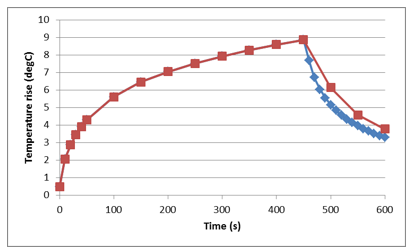
For a single device exposed to the EM field from the RF coil, heating of a stent is transient in nature. The maximum temperature rise is observed at the ends of the stent, Figure 5.3.
Figure 5.3: Transient heating of stent exposed to EM field of RF coil in an MRI.
Simulations of this type have been used to identify configurations of implanted devices that provide the highest temperature rise such that physical testing is then performed around that peak. This drastically limits the number of tests that need to be performed and the justification for a limited number of tests to support safety labeling requirements.
Because the thermal response of a device, due to exposure to the MRI field, can be simulated, the effect of the body’s ability to dissipate heat can also be included. Practically, there are two main mechanisms by which thermal dissipation would be expected to occur: perfusion from the tissue around the stent and dissipation of heat due to flow of blood over a stent located in an artery or vein.
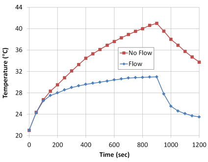
To investigate this response, simulations of RF induced heating of a stent with fluid arterial or vascular flow have been performed, Figure 5.4.
Figure 5.4: Effect of fluid flow in temperature rise of a stent exposed to EM field of an RF coil in an MRI.
As might be expected, blood flow significantly reduces the peak temperature as well as the rate at which the peak temperature is achieved. Further studies indicate that the temperature rise can also be affected by the rate, uniformity and pulsed nature of any fluid flow over the stent when exposed to an MRI field.
Although these analyses have been performed assuming material with uniform material properties around the stent, the effect of the body’s structure and the associated inhomogeneities of material properties can also be simulated. The human body is a mixture of tissue, bone and organs all of which have different electrical and thermal properties. Given the inhomogeneity of the structure of the human body, questions arise about how this variation may affect heating of devices placed in locations that are typical of their intended use.
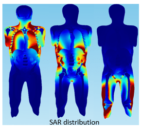
Scans of a human body can be imported into a simulation and material properties assigned to the various tissues, organs and skeletal structures. The Specific Absorption Rate (SAR) distribution, Figure 5.5, demonstrates how the inhomogeneity of tissue properties affects the absorption of RF power from an MRI.
Figure 5.5: SAR distribution of human torso exposed to MRI EM field.
Precise calculation of SAR is mathematically complex and related to factors such as field strength, RF power, tissue properties, and body size among others. While not directly related to heating of implanted devices, SAR does show inhomogeneity in the distribution of RF power in the human body and thus that you might expect the location of a device in the body to affect the extent of heating. In simulations, medical devices can be placed in specific locations in the body in which they would typically be used and the influence of local body structure on SAR distribution and any device heating evaluated.
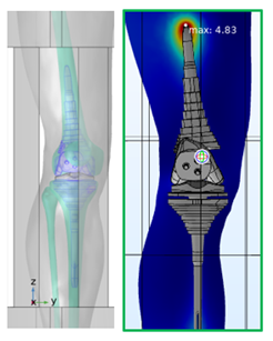
In Figure 5.6, a knee replacement has been imported into a simulation of RF heating and located in a typical area of use. Subsequent simulations of the effect of exposure to the EM field of the RF coil and the resulting temperature rise indicate that a maximum T rise of just under 5 degrees may be expected.
Figure 5.6: Knee implant in RF heating simulation.
Overall, we see that device heating due to exposure to the RF field of an MRI is a complex phenomenon, but by careful use of simulation we can identify the influence of device design, guide the use of testing for safety labeling and provide an understanding of the role of the human body in affecting the exposure to RF power and dissipating heat generated in the vicinity of any implanted device.
Hopefully this has provided some examples of where simulation can help in the various stages of development and use of medical devices. This is a rapidly developing field as the ability to integrate predictive physics with the complexity associated with the variability in the human body increases.

