Incorrect boundary conditions in finite element analysis (FEA) lead to incorrect solutions, or the simulation does not converge. To develop a converged solution, all FEA models require constraining each dependent variable somewhere in the model. Typically, this is done directly onto the model region geometry, but it can also be accomplished through Robin conditions. This boundary condition specifies the dependent variable external to the boundary condition location. One example of a Robin condition is a convective heat flux boundary condition where the ambient temperature outside the model region is constrained. Without these constraints, there will be many solutions to the problem posed, and the COMSOL Multiphysics solvers will almost invariable return an error message.
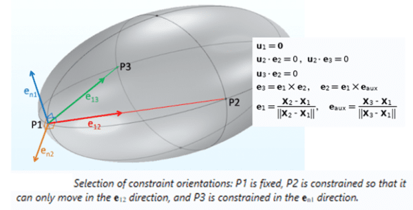
In Solid Mechanics models where the dependent variable is displacement, this process of applying constraints is referred to as rigid motion suppression and requires a little extra thought, especially in 3D. Displacement degrees of freedom are solved in each spatial direction, therefore the analyst needs to constrain the motion in all directions. Additionally, since solid elements do not directly solve for rotations as a separate degree of freedom, the displacement constraints need to be selected strategically, so that rigid body rotations are suppressed. The analyst also does not want to over-constrain motion because this can be unphysical and can introduce inaccuracy into the predictions.
Many systems are glued, bolted, welded or otherwise tied to some additional structure. The location of these connections provides a natural choice for accurately constraining displacements. However, it is also common to encounter scenarios where objects are free to slide and move, depending on the magnitude of the forces they experience. Think of the coffee cup currently resting on the table next to your hand; an accidental bump and you’ve got coffee on your keyboard!
Without a bump, the cup will not move because of stabilizing gravitational forces leading to tangential frictional effects resisting horizontal sliding.
From a modeling perspective, we could include these stabilizing effects by adding a contact feature and gravitational body loads in the analysis. Typically, for an unconstrained thermal stress analysis, this would unnecessarily overcomplicate the model. In situations like this, we recommend using the predefined “Rigid Motion Suppression” feature available with the base COMSOL Multiphysics package. This feature adds the minimum number of constraints required to suppress any rigid body motions. The points and directional constraints are automatically selected so there will be no reaction forces if there are no external loads, or the external loads are self-equilibrating.
This feature is particularly useful for unconstrained thermal stress analyses where the only stresses that develop are due to gradients in thermal strain. These gradients may be due to temperature gradients in the system or to disparities in the coefficient of thermal expansion of different materials. Either way, the important thing is that the rigid motion suppression constraints do not introduce additional unphysical forces that would corrupt the accuracy of the model.
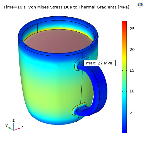
Below is a plot of thermal stresses in a ceramic coffee cup due to the thermal shock of hot coffee being poured into the mug. After 10 seconds, the maximum stress at the root of the handle is predicted to be 27 MPa.
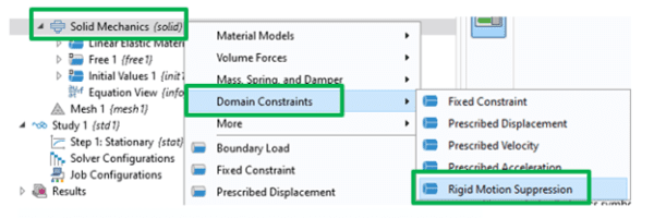
Instead of stabilizing this model with gravity and non-linear frictional contact conditions, the rigid motion suppression feature was added by right-clicking on Solid Mechanics and selecting Domain Constraints > Rigid Motion Suppression, as shown below:
For detailed and comprehensive training in solving Structural Mechanics problems in COMSOL Multiphysics (including ones like this), consider taking AltaSim’s Structural Mechanics Solutions using COMSOL Multiphysics course.


