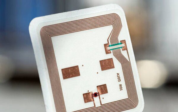
Radio Frequency Identification (RFID) technology has been around for more than 50 years and continues to evolve. Today, the technology uses electromagnetic fields to automatically identify, and track tags attached to both inanimate objects and living creatures.
The great appeal of RFID technology is that unlike bar codes, it allows information to be stored and read without requiring either contact or a line of sight between the tag and the reader. It’s used in a multitude of industries from retail to track or identify consumer products and their packaging to tracking surgical tools and materials in the healthcare industry to ensure nothing is accidentally left inside the patient.
The RFID technology is made up of two-way radio transmitter-receivers called interrogators or readers, and they send a signal to the tag and read its response.
The reader antenna generates an electromagnetic field that energizes a chip (IC-circuit) inside the tag. The electromagnetic field is modulated by the tag’s circuit and the modulated signal is recovered by the reader antenna. RFID is most often used in one of these four frequency bands:
- Low Frequency (LF) 125 to 134 kHz Band
- High Frequency (HF) 13.56 MHz
- Ultra-High Frequency (UHF) 433 MHz and 860 to 956 MHz band
- Microwave Frequency 2.45 to 5.8 GHz band
Synthesize & Optimize RFID Transmit/Receive & Asset Tag Antennas with Simulation
Through our COMSOL Multiphysics simulation expertise, we can test and analyze results to evaluate how well the design of an RFID tag performs. Antenna geometry and material properties can be fully parametrized to study the effect of design parameters on RFID performance and to maximize coupling (i.e., S21).
AltaSim’s RFID simulation in COMSOL process includes, but is not limited to:
- Flexible RF module and numerically efficient set of tools for simulation of Transmitter (TX) and Receiver (RX) high frequency antennas
- Excite antenna and get access to important lumped parameters such as S11 (power reflectance coefficient) and S21 (power transmittance coefficient from TX to RX) with Lumped Port boundary condition
- Tune RX and TX to resonate at a specified operational frequency with S11 parameter
- Optimize the energy coupling between TX and RX with S21 parameter
- Antenna trace of a finite thickness to effectively and accurately model as surface using Transition Boundary Condition to account for resistive losses
- Easily include RLC circuitry into the model for finite tuning of the antenna resonance frequency with Lumped Element boundary condition
- Calculate resistive, polarization, and radiation losses with modeling tools
- Obtain Radiation Pattern plot and antenna polarization with special Far-Field Calculation modeling feature
- Facilitate antenna design with Smith Plot special post-processing tools
- Optimization interface and set of special Optimization Solvers for RFID design purposes
AltalSim provides diverse experience and specializes in computational simulations, including RFID simulation. Contact us today to get real-world advice and recommendations and the flexibility to solve issues independently or with us by your side.


