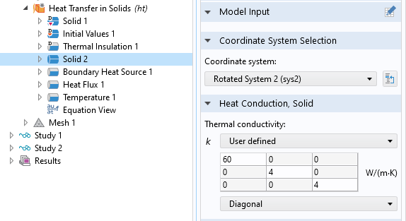
Many of the simulations we have developed through the years include materials that behave anisotropically. This class of materials has different material properties in different directions. This anisotropy often needs to be included in computational models to achieve the desired level of accuracy in the simulation outputs. If the material coordinate system of the anisotropic properties is not aligned with the global coordinate system in the model, a transformation must be performed to convert the material property matrix to the equivalent matrix in the global coordinate system. For many material properties, COMSOL Multiphysics has a built-in option to select the coordinate system used for anisotropic properties (see Fig. 1). This selection specifies the coordinate system in which the material properties are entered, and the software automatically transforms the material property matrix to the global coordinate system.
Fig. 1. Selection of coordinate system for anisotropic material properties.
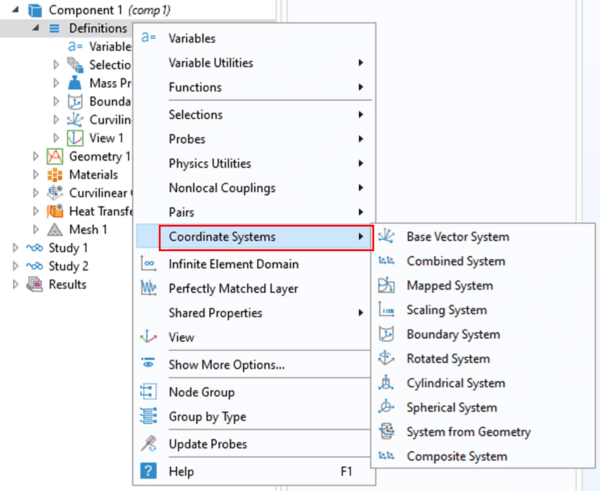
To use this approach, the simulation engineer needs to develop a coordinate system that can be used for the anisotropic material. User-defined coordinate systems can be created by right-clicking on the Definitions node and selecting one of the options in the Coordinate Systems sub-menu (see Fig. 2). The appropriate type of system depends upon the manner in which the material coordinate system varies spatially. Once a coordinate system has been defined under the Definitions node, it is available for selection in any coordinate system drop-down lists in the physics settings.
Fig. 2. Types of coordinate systems that can be created under the Definitions node.
If the material coordinate system does not conform to any of the pre-defined options available on the Definitions node, the Curvilinear Coordinates interface can be used. This interface is added from the Mathematics section of the Add Physics window, and it can solve for the spatial distribution of the basis vectors using a variety of methods. When the “create base vector system” option is activated (see Fig. 3), a Curvilinear System node is generated under the Definitions node, and this coordinate system is available for use in other physics interfaces. The curvilinear coordinate system must be calculated using a stationary study step prior to the calculation of the physics in which it is used. For an example of the use of the Curvilinear Coordinates interface with anisotropic material properties, see the model “Anisotropic Heat Transfer through Woven Carbon Fibers” in the COMSOL Multiphysics Application Library.
Fig. 3. Settings for the Curvilinear Coordinates interface.
Anisotropic materials are typically an advanced modeling feature, and AltaSim develops these types of simulations for our clients regularly. If you have been frustrated by including anisotropic materials into your simulations, then please contact us so we can review your simulations with you as part of our consulting services.
If you are seeking to learn more about the basics of developing simulations, then you could benefit from our MP Solutions class. The next class is Dec 6-15, 2022. Click here to learn more and register.


