Many industries face increased thermal challenges with their electronic products. Customers often want devices with smaller form factors and higher functionality, but these changes create higher thermal fluxes and power density, which in turn require better thermal management to prevent device failure.
From the electrical designer’s standpoint, getting traction on thermal problems may be difficult: estimating heat transfer rates before prototypes are available is not trivial, and even after prototypes are made, waiting for sufficient testing can be time consuming. As an example, even when a designer is armed with the knowledge of nominal power dissipation and enclosure geometry, there remains the pesky detail of leakage power. The leakage current is actually dependent on operating temperature, so if the junction gets too warm, power dissipation can rise exponentially creating ‘thermal runaway’ and without sufficient testing or simulations to the contrary, thermal runaway is a significant concern.
At AltaSim, we recommend identifying the thermal budget and then performing a feasibility analysis.
To determine the thermal budget, one simply needs to identify the following variables, and perhaps whether they are flexible or fixed: external ambient air temperature, Ta, component maximum junction temperature, Tj, component package case temperature, Tc, dissipation power, P, including the dependence of leakage current on Tj, package thermal performance characteristics θjc and θjb, and what system-level guardbands are used (such as for temperature, performance, etc). If the system relies on natural convection cooling (air motion to transport heat when no fan is present), then the allowed orientations of the product are also important. For example, whether the product must operate when turned on its side is relevant if natural convection is being utilized.
Once a thermal budget is identified, the next step is a feasibility analysis. For a new product, or a new thermal solution,a feasibility study can be useful and insightful. However, if a thermal solution has already been optimized for a particular design, and maybe even re-optimized, then a feasibility analysis is too coarse of a tool.
To do a thermal feasibility analysis for a new design before a prototype is built, a hand calculation can be used as a simple check to determine whether the junction temperature will be in the right ballpark. Oftentimes, a hand calculation provides a means to bracket the problem, that is, to determine the range of possible resulting temperatures. Leakage current can be included by using an iterative approach, as long as the dependence of leakage current on junction temperature is known. For more complex designs, computational analysis is a way to incorporate design details and determine the associated temperatures during operation.
If the feasibility analysis shows that the bracketed solution space will keep temperatures low, then one can move to further optimization for cost or manufacturability, etc. But if the feasibility comes out borderline or too warm, then either an improved thermal design or a more in-depth analysis may be required. Another option could be using active monitoring and control techniques (throttling) for the electronics if the system can function with less power during certain intervals and successfully operate in a transient state.
To do a feasibility analysis, the idea is to use the relevant thermal equation(s) to do a preliminary check of the overall thermal design. The steady state behavior can be predicted using a thermal resistance approach. If transient behavior (spikes in power) is anticipated, then operational periods should be compared to the thermal time constant. As long as the bursts of high-power activity are shorter than the thermal time constant, and they are followed by long periods at low power (providing time to cool), then the system will not exceed the steady state maximum temperature.
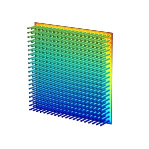
Let’s consider a simple electronic system used in continuous operation mode: A single component package system that utilizes a heat sink cooled by natural convection, using an upward air flow (chimney style convection). Here, one could use q=hA(ΔT) where q is the thermal dissipation of the component in Watts, A is the surface area of the heat sink (including base) in square meters and the heat transfer coefficient (in W/m2K) is estimated with a range of possible values, instead of a single value, due to the difficulty of predicting an exact value. An estimate of the operating temperature rise can be obtained by solving for ΔT, the temperature of the base of the heat sink minus the ambient (inlet) temperature, here in degrees Celsius. If the thermal resistance of the component itself, and the Thermal Interface Material (TIM) between the component and the heat sink are small compared to the thermal resistance due to natural convection, then the resulting ΔT will be a good, but still somewhat rough, approximation that serves to check that the design is feasible. Then down the road, including at least a bit of future design optimization would help ensure that the product would perform in the approximate temperature range predicted.

In the next blog, a description of using a thermal resistance network to quantify system behavior and determine system-level feasibility will be given. The approach is useful because it aids system-level understanding. For example, if you want to increase power dissipation while maintaining the junction temperature constant, this can be achieved by decreasing the overall system thermal resistance. We hope that you enjoyed this blog. Please feel free to contact us if you have questions about thermal analysis of electronics or feasibility studies in general, or if you would like to discuss thermal aspects of your application.
